
Bayaanka Asturnaanta
Lithium battery protection board is the charge and discharge protection for the series lithium battery pack; when fully charged, it can ensure that the voltage difference between each unit battery is less than the set value (generally ±20mV), and realize the equalization of each unit of the battery pack. , effectively improving the charging effect in the series charging mode; simultaneously detecting the overvoltage, undervoltage, overcurrent, short circuit, and overtemperature conditions of each single cell in the battery pack, protecting and extending the battery life; undervoltage protection enables each A single battery prevents damage to the battery due to overdischarge during discharge.
The finished lithium battery consists mainly of two major parts, a lithium battery core and a protective plate. The lithium battery core is mainly composed of a positive electrode plate, a separator, a negative electrode plate and an electrolyte; the positive electrode plate, the separator and the negative electrode plate are wound or laminated, packaged, and poured into the electrolyte. After the package is made into a battery core, the role of the lithium battery protection board is not known to many people. The lithium battery protection board, as the name implies, is used to protect the lithium battery. The role of the lithium battery protection board is to protect the battery but not charge it. Stream, there is output short circuit protection.
Lithium battery protection board technical parametersEquilibrium current: 80mA (when VCELL=4.20V)
Equilibrium control point: 4.18±0.03 V overcharge threshold: 4.25±0.05 V (4.30±0.05 V optional)
Over-discharge threshold: 2.90±0.08 V (2.40±0.05 V optional)
Over discharge delay: 5mS
Over discharge release: disconnect the load, and each cell voltage is higher than the over-discharge threshold;
Overcurrent release: disconnect load release
Over temperature protection: There is an interface, and a recoverable temperature protection switch needs to be installed;
Working current: 15A (according to customer choice)
Static power consumption: "0.5mA
Short-circuit protection function: It can protect and disconnect the load and recover itself.
Main functions: overcharge protection function, over discharge protection function, short circuit protection function, over current protection function, over temperature protection function, balanced protection function.
Interface definition: The charging port and the discharging port of the board are independent of each other, the two are common to the positive pole, B- is the negative pole connecting the battery, C- is the negative pole of the charging port; P- is the negative pole of the discharging port; B-, P-, C - The pads are all via type, and the pad holes are all 3 mm in diameter; the battery charge detection interfaces are output in the form of DC pins.
Parameter description: Configuration of maximum working current and overcurrent protection current value, unit: A (5/8, 8/15, 10/20, 12/25, 15/30, 20/40, 25/35, 30/50 , 35/60, 50/80, 80/100), special overcurrent values can be customized according to customer requirements.
Lithium battery protection board principleThe reason why lithium batteries (fillable) need protection is determined by its own characteristics. Because the material of the lithium battery itself determines that it can not be overcharged, overdischarged, overcurrent, short circuited and ultra-high temperature charge and discharge, the lithium battery lithium battery assembly will always follow an exquisite protection board and a current fuse.
The protection function of the lithium battery is usually completed by the protection circuit board and the current device such as the PTC. The protection board is composed of electronic circuits, and the voltage of the battery core and the charging and discharging circuit are accurately monitored at -40 ° C to +85 ° C environment. Current, timely control of the current circuit on and off; PTC in the high temperature environment to prevent battery damage.
Ordinary lithium battery protection boards usually include control ICs, MOS switches, resistors, capacitors, and auxiliary devices FUSE, PTC, NTC, ID, memory, and so on. The control IC controls the MOS switch to be turned on under all normal conditions, so that the cell and the external circuit are turned on, and when the cell voltage or the loop current exceeds a prescribed value, it immediately controls the MOS switch to turn off, and protects the cell. Safety.
When the protection board is normal, Vdd is high level, Vss, VM is low level, DO and CO are high level. When any parameter of Vdd, Vss, VM is changed, the level of DO or CO will be A change has occurred.
1. Overcharge detection voltage: In the normal state, Vdd gradually rises to the voltage between VDD and VSS when the CO terminal changes from a high level to a low level.
2. Overcharge release voltage: In the state of charge, Vdd gradually decreases to the voltage between VDD and VSS when the CO terminal changes from low level to high level.
3. Overdischarge detection voltage: In the normal state, Vdd gradually decreases to the voltage between VDD and VSS when the DO terminal changes from high level to low level.
4. Overdischarge release voltage: In the overdischarge state, Vdd gradually rises to the voltage between VDD and VSS when the DO terminal changes from low level to high level.
5. Overcurrent 1 detection voltage: In the normal state, the VM gradually rises to the voltage between VM and VSS when DO changes from high level to low level.
6. Overcurrent 2 detection voltage: In the normal state, the VM rises from OV at a speed of 1 ms or more and 4 ms or less to the voltage between VM and VSS when the DO terminal changes from a high level to a low level.
7. Load short-circuit detection voltage: In the normal state, the VM rises at a speed of 1 μS or more and 50 μS or less from OV to the voltage between VM and VSS when the DO terminal changes from a high level to a low level.
8. Charger detection voltage: In the overdischarge state, the VM gradually drops to OV and the VM-VSS voltage changes from low level to high level.
9. Current consumption during normal operation: In the normal state, the current flowing through the VDD terminal (IDD) is the current consumption during normal operation.
10. Over-discharge current consumption: In the discharge state, the current flowing through the VDD terminal (IDD) is the over-current discharge current consumption.
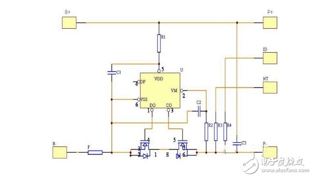
1. Normal state: The battery voltage is above the overdischarge detection voltage (2.75V or more), the overcharge detection voltage is below (4.3V or less), and the voltage of the VM terminal is above the charger detection voltage. Overcurrent/detection When the voltage is below (OV), the IC controls the MOS transistor by monitoring the voltage difference between VDD and VSS and the voltage difference between VM and VSS. The DO and CO terminals are both high and the MOS transistor is turned on. At this time, you can charge and discharge freely;
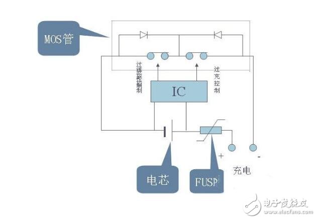
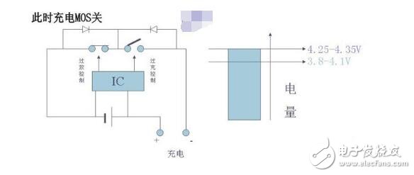
When the battery is charged so that the voltage exceeds the set value VC (4.25-4.35V), VD1 flips to make Cout low, T1 is turned off, charging stops, and when the battery voltage falls back to VCR (3.8-4.1V), Cout It goes high, T1 turns on and continues to charge, VCR is less than a fixed value of VC to prevent the current from jumping frequently.
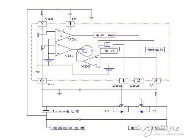
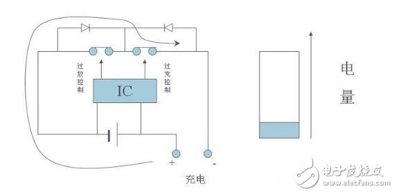
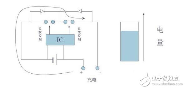
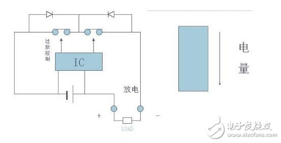
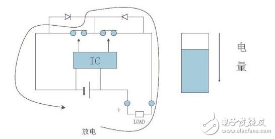
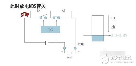
When the battery voltage drops to the set value VD (2.3-2.5V) due to discharge, VD2 flips, and after a short time delay fixed inside the IC, Dout becomes low level, T2 is turned off, and discharge stops.
When the circuit discharge current exceeds the set value or the output is short-circuited, the overcurrent and short circuit detection circuits operate to turn off the MOS transistor (T2) and the current is turned off.
The protection loop consists of two MOSFETs (T1, T2) and a control IC (N1) plus some RC components. control
The IC is responsible for monitoring the battery voltage and loop current, and controlling the gates of the two MOSFETs. The MOSFETs act as switches in the circuit and are controlled separately.
The charging circuit and the discharging circuit are turned on and off, and C2 is a time delay capacitor. The circuit has overcharge protection, over discharge protection, over current protection.
Protection and short circuit protection function, its working principle is analyzed as follows:
Ku soo dir alaab-qeybiyahan

Bayaanka Asturnaanta

Buuxi macluumaad dheeri ah si markaa si dhakhso leh ula xiriiri karto
Bayaanka Asturnaanta